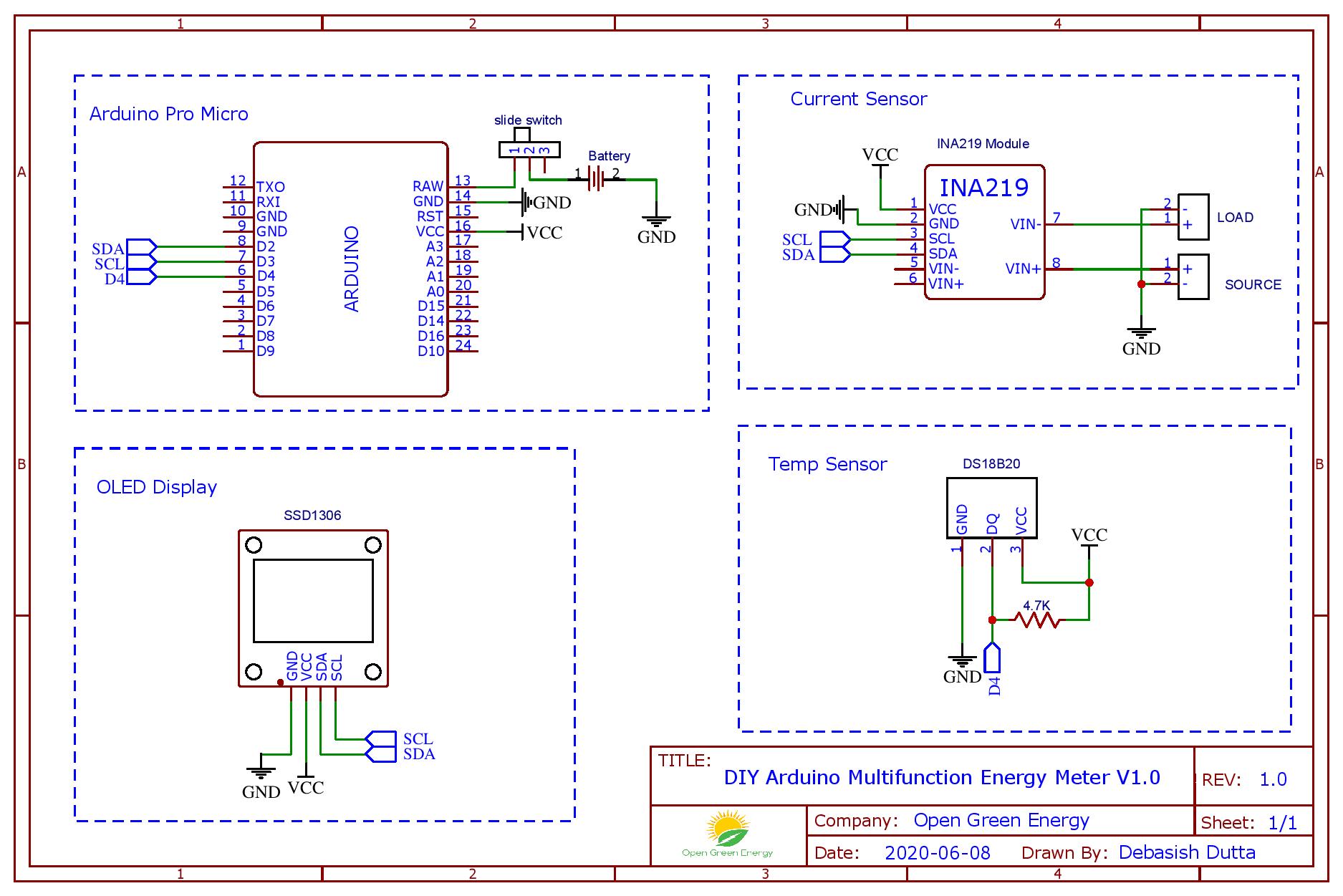

The majority of the sensors we use in our projects are breakout boards with resistors already built in. Typical values for 5V devices are 4.7k Ohm and 2.4k Ohm for 3.3V devices. One is used to send and receive data(SDA), while the other is used to send the clock signal (SCL).īecause the SDA and SCL lines are active low, resistors should be used to draw them up. The I2C communication protocol sends and receives data via two wires. Ultra Fast-Mode (UFm), with a bit rate of up to 5 Mbit/s.High-speed Mode (Hs-mode), with a bit rate up to 3.4 Mbit/s.Fast-Mode Plus (Fm+), with a bit rate up to 1 Mbit/s.Fast-Mode (Fm), with a bit rate up to 400 kbit/s.Standard-Mode (Sm), with a bit rate up to 100 kbit/s.Standard-mode, Fast-mode (Fm), Fast-mode Plus (Fm+), and High-speed mode (Hs-mode) Over time there have been several additions to the specification so that there are now five operating speed categories. The I2C-bus was limited to 100 kbit/s operations. External EEPROMs, Digital Temperature Sensors, LCD Controllers, OLED Displays, RTCs, and other components are also available. It’s commonly used in short-distance intra-board communication to connect lower-speed peripheral ICs to processors and microcontrollers. The I2C bus is a synchronous, bidirectional, half-duplex serial communication bus with many masters and slaves. I2C (i-square-c) stands for “Inter-Integrated-Circuit,” and it was invented in 1982 by Philips Semiconductors (now NXP). We’ll go through how ESP32 I2C works, how to alter the default I2C pins (SDA, SCL), how to connect numerous I2C devices on the bus with proper addressing, and how to make an ESP32 I2C scanner to check for available I2C devices on the bus and obtain their addresses.

In this article we will learn to use the ESP32 I2C communication protocol (in Arduino IDE).


 0 kommentar(er)
